Welcome to the user manual for the ATtiny3224 development board. This guide will walk you through the steps needed to get started with programming the ATtiny3224 Microcontroller. Below are some of the components needed to successfully program the ATtiny3224 development board using Arduino IDE. MegaTinyCore
It is an excellent library written by SpenceKonde that provides support for the tinyAVR microcontrollers (Which is a newer series of AVR) out of which for our specific application, we use the ATtiny series of microcontrollers (ATtiny 0, ATtiny 1 and ATtiny 2).
Simplifies programming ATtiny microcontrollers using the familiar Arduino environment.
By using MegaTinyCore, you can efficiently develop software for ATtiny microcontrollers without needing to delve into complexities of low-level programming. UPDI Programmer with Serial monitor feature: This tool is essential for programming the development board. The Serial monitor feature provides ability of monitoring serial output from the ATtiny microcontroller UART using the Arduino IDE.
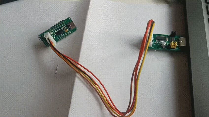
Fig.a Fig.b Purpose: This is the setup for programming and monitoring a microcontroller (ATtiny 3224). Components: Computer:
Computer (can be Windows, Linux or Mac) used to run the Arduino IDE. It is used in programming the microcontroller board. Microcontroller Board: The target device being programmed and monitor is ATtiny3224 development board. Programmer Cable: This cable is used to connect the microcontroller board to the UPDI programmer. At a minimum this cable has VCC, UPDI and Ground connections to the microcontroller board. Connections: The UPDI programmer is connected to the computer using the USB port. The microcontroller board is connected to the UPDI programmer via a Programmer cable.
Setting up the Arduino IDE for programming ATtiny3224
The USB Serial UPDI programmer is used to download the sketch to the development board.
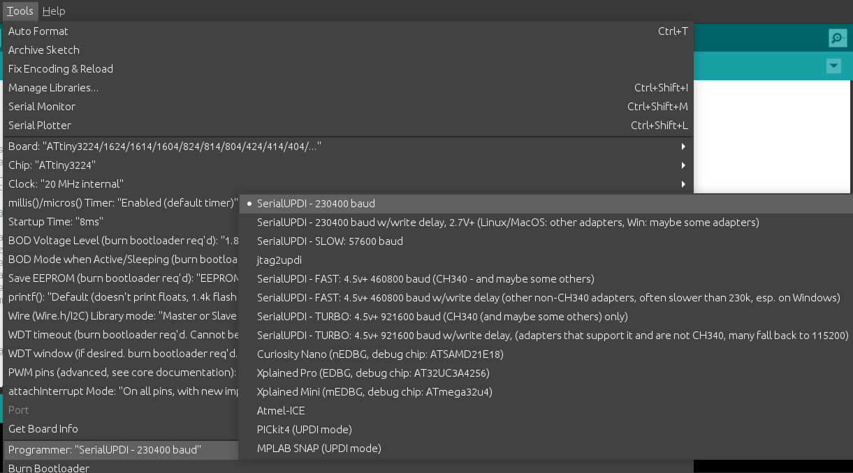
Choose "SerialUPDI (230400 baud)" in the “Programmer” option under “Tools” menu of Arduino IDE.
Fig.c
Note: At 3.3V the microcontroller frequency is limited to maximum of 8 – 10 Mhz. At 5v 20MHz operation is possible.
🛠️ Getting started with UPDI programmer
📘 Overview
⚙️ Setup
Setting up Arduino IDE on Linux (Ubuntu)
Needed only once to setup Arduino IDE for programming ATtiny3224
Install Arduino IDE 1.8.19 from Arduino website or respective distro/OS software center.
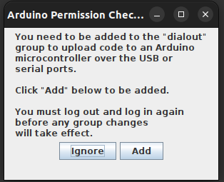
Launch the Arduino IDE you shall get following pop-up as fig.1, click add. (to take effect logout from your user account login back to the user account, now it is good to go)
|
Fig.1 |
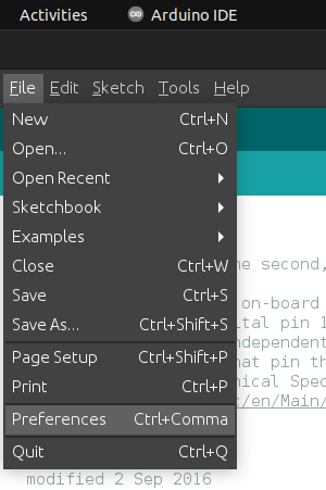
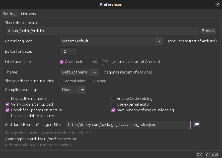
Install library of “megaTinyCore” by Spence Konde on to Arduino IDE, to add use the URL “https://drazzy.com/package_drazzy.com_index.json” library in the Arduino additional library option present in
“Files --> Preferences(Fig.2) --> Additional Boards Manager URLs (Fig.3)”
|
|
Fig.2 |
Fig.3 |
Note: In Ubuntu it has been observed that “brltty” package does not allow the UPDI’s USB to be attached to the machine, following error is observed in dmesg output.
|
Fig. 4 |
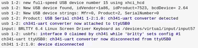
Use the following command to resolve and the UPDI will be attached to ‘/dev/ttyUSB0’
sudo apt remove brlttyNow goto
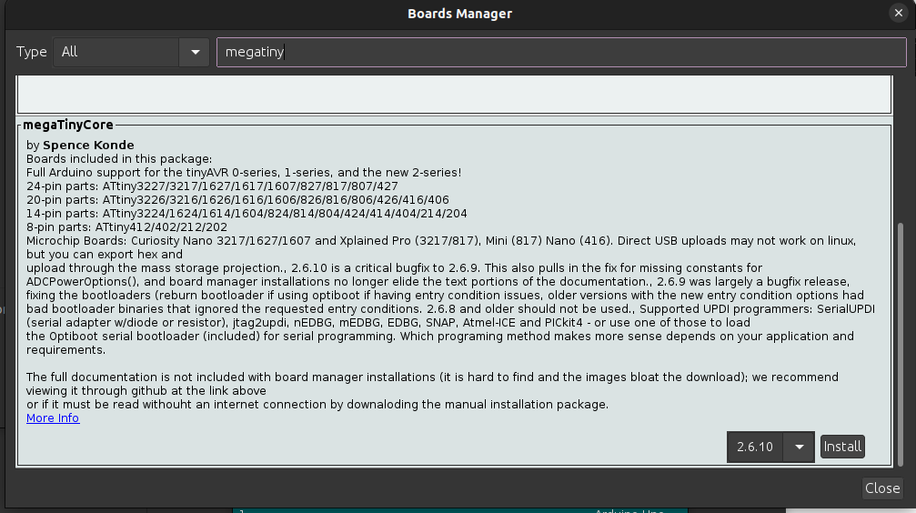
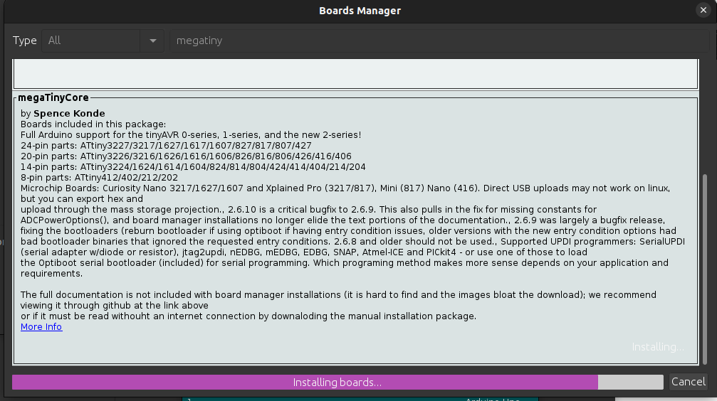
and click install.“Tool” --> Board --> Boards Manager and search for “megaTinyCore” (using 2.6.8 version)
|
|
Fig.6 |
Fig.7 |
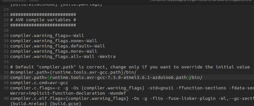
Now edit “platform.txt” file in folder location as
(in linux) comment the following line/home/USER_NAME/.arduino15/packages/megaTinyCore/hardware/megaavr/2.6.8/”
and add below it following line“compiler.path={runtime.tools.avr-gcc.path}/bin/”
as shown in Fig.8.“compiler.path={runtime.tools.avr-gcc-7.3.0-atmel3.6.1-azduino6.path}/bin/”
|
Fig.8 |
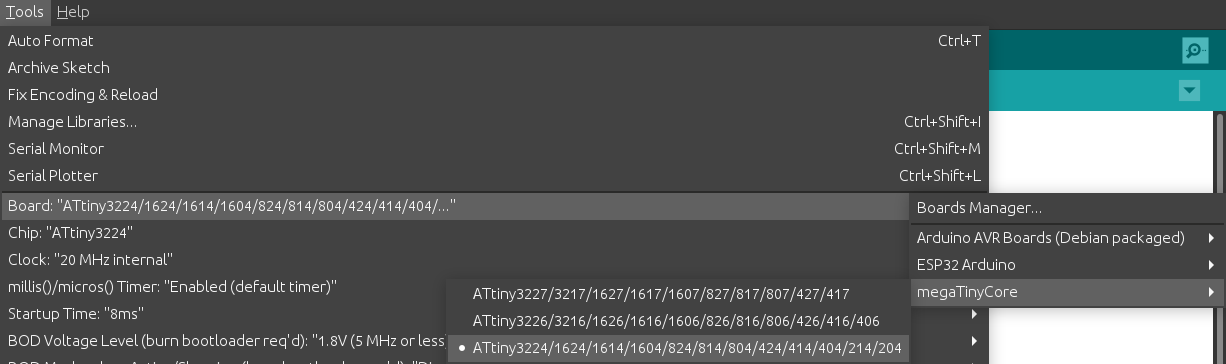
Now goto
“Tools” menu --> Boards --> megaTinyCore --> ATtiny3224
|
Fig.9 |
Now Arduino IDE is ready to program and monitor ATtiny3224 microcontroller.
💻 Usage
UsageSteps below show the programming steps using Provenant systems UPDI programmer
Use the Arduino IDE to create your program. For example, start with a simple LED blinking sketch.
Ensure the jumper is in the ON position to enable programming mode.
Connect the programmer to USB port on the computer
Connect the programmer to the development board using the provided cable
Ensure the power switch on the UPDI programmer is set to OFF if the development board gets external power, else select it to ON position to have the UPDI programmer provide power the development board
Select the appropriate communication port under “Tools” menu. (refer Fig.c)
Upload your code to the microcontroller using “Sketch” => “Upload” option.
To observe serial output from the microcontroller program, remove the jumper to switch to serial monitoring mode.
Open the Arduino Serial Monitor to view the output from your microcontroller's code.
Note: When the jumper cap is ON, the receiver and transmitter pins are disabled, and the USB connection is redirected to the UPDI pins for programming.
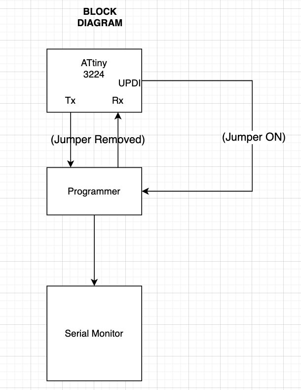
Flow Diagram of the UPDI & Serial monitoring mode
|
1.Tx: Transmitter 2.Rx : Receiver 3.UPDI (Unified Program Debug Interface): Used to program when the jumper is ON. |
🔄 Sample Sketch & Arduino IDE pin assignment
Sample Code: LED BLINKING
void setup() {
Serial.begin(115200); //initialize digital pin LED_BUILTIN as an output.
pinMode(LED_BUILTIN, OUTPUT);
}
// the loop function runs over and over again forever
void loop() {
digitalWrite(LED_BUILTIN, HIGH); // turn the LED on (HIGH is the voltage level)
Serial.printf("LED ON\r\n");
delay(100); // wait for a fraction of second
digitalWrite(LED_BUILTIN, LOW); // turn the LED off (LOW is the voltage level)
Serial.printf("LED OFF\r\n");
delay(1000); // wait for a second
}
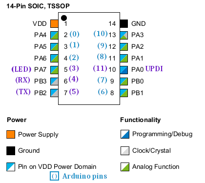
Below is the Arduino Pin configuration with refrence ATtiny 3224 pinout
-
Arduino Pin Assignment
Arduino Pin ATtiny Pin Number Comments 0 2 PA4 1 3 PA5 2 4 PA6 3 5 PA7 [LED_BUILTIN] 4 6 PB3 [Rx] 5 7 PB2 [Tx] 6 8 PB1 7 9 PB0 8 11 PA1 9 12 PA2 10 13 PA3 11 10 PA0 [UPDI]
Image reference of Arduino IDE pin assignment for ATtiny 3224 14-pin microcontroller
|
❓ FAQ
Q: My board isn't responding.
A: Check power and UPDI pin connection.